


Load combination AASHTO group X = DL + ( LL + I ) + E with no increase in allowable unit stress will followed for the purpose of analysis, it is usual practice to consider one foot width of the box.
The culvert is subjected to the following load case for which moments, thrusts and shears have been calculated.
1.Live load, dead load and earth pressure acting from outside and no hydrostatic pressure acting from inside.
2.Live load, dead load and earth pressure acting from outside and hydrostatic pressure acting from inside.
3.Dead load and earth pressure acting from outside and hydrostatic pressure acting from inside.
The loading cases are shown systematically for loading combination as mentioned above.
Let, the thickness of the vertical and horizontal slab is 9 inches.

CASE-1 :
Dead load, live load and earth pressure acting from outside and no hydrostatic pressure from inside.
3.1.4 TOP SLAB LOAD :
The weight of top slab, filling earth, two outer and two inner walls with live loads are assumed to be uniformly distributed over foundation.
1. Weight of top slab = ( 9/12 )X( 150/1000 )
= 0.1125 k/ft 2
2. Weight of fill (8 ft) = 8*0.12*0.7 [ as per PCA manual page no.38, earth load may be taken as 70% of its actual load.]
= 0.672 k/ft2
≈ 0.7 k/ft2
3. Wearing coarse = ( 2/12 )*( 120/1000 )
= 0.02 k/ft 4
Total = ( 0.1125+0.7 +0.02 ) k/ft2
=0.81 k/ft2
3.1.5 LIVE LOAD :
E = 4+0.06S
Where, S = Effective span in ft.
E = Effective width which should not be greater than 7 ft.
As per AASHTO 92 section 8.8.2,
In analysis of continuous and rigid frame members, distances to the geometric centers of members shall be used in the determination of moments.
Therefore the dimensions of center line,
Vertically = 4.75 ft = 57 inches
Horizontally, S = 4.75 ft = 57 inches
In case of exposed slab:
Effective width, E = 4+0.06S
= 4.29 ft <7 ft

CHAPTER - 3
DESIGN OF BOX CULVERT
3.1 DESIGN OF ONE UNIT BOX CULVERT

When the depth of fill is 2’ or more, concentrates load is to be uniformly distributed over a square, the side of which are equal to 1.75 times the depth of fill, shear is calculated as for dead load when the depth of fill is less than 2’, AASHTO specifies that the wheel load be distributed as an exposed slab.
When areas from several concentrations overlap, total load is considered uniformly distributed over the area, defined by the outside limits of the individual area. The total width of distribution should not exceed the total width of supporting slab. For single span the effect of live load may be neglected when the fill is more than 8’ and exceeds the span length. For multiple spans, the live load may be neglected when the depth of fill exceeds the distance between end supports or abutment.
If the calculated live load and impact moment (based on a distribution loading) exceeds the live load and impact moment due to a concentrated load, the lower values should be used.
3.1.1 SPECIFICATION DATA :
- Water way opening = 1 cell ( 4 ft * 4 ft )
= 4 * 4 ft2
= 16 ft2
2. Foundation type-unyielding foundation
3. Live load—HS-20-44
4. Height of fill above slab = 8 ft.
3.1.2 DESIGN CRITERIA :
1. Unit weight of concrete = 150lb/ft
2. Unit weight of soil = 120lb/ft
1. Compressive stress of concrete at 28 days, f/c = 3000psi
2. Allowable compressive stress, fc = 0.45 f/c
= 1350 psi
3. Yield point stress of reinforcement, fy = 60,000psi
4. Allowable stress of reinforcement, fs = 0.4fy
= 24,000psi
3.1.3 DESIGN CONSTANT :
n = Es /Ec
= 29 * 10 /( 57000*3000 )
= 9.28
≈ 9
r = fs / fc
= 24,000 / 1350
= 17.78
k = n / (n+r)
j = 1- k/3
= 0.888
R = 0.5 X fc X k X j
= 0.5 X 1350 X 0.336 X 0.888
= 201
. .. n = 9
k = 0.336
j = 0.888
R = 201


CHAPTER-2
BOX CULVERT
2.1 DEFINITION OF CULVERT :
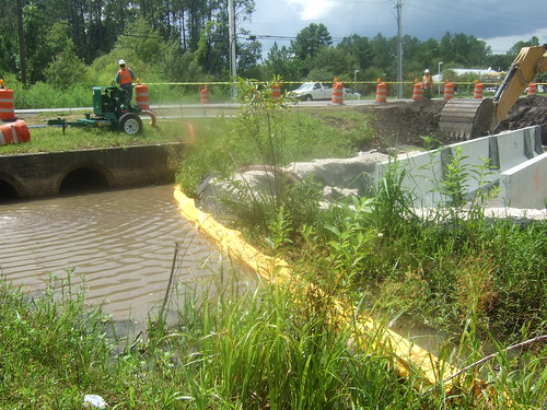
Culverts refer to the structures provided across a watercourse for the purpose of passing the flow from one side of the road or railway line to the other side without any detriment or damage to the approach embankments.
A culvert can be defined as a bridge with a total length not exceeding 8m between the faces of abutments or extreme vent way boundaries when measured at right angles to the axis of vent way.
Before structure of this nature is put up, it is necessary to consider the following factors--
1. The need for the structure and its location.
2. The traffic that will pass over the structure on completion and in future (in respect of the volume of traffic as well the axle/wheel load).
3. Characteristics of the stream/river/canal.
4. Subsoil condition.
5. Alternative site either by longitudinal shift of the proposed structure or by lateral shift of the alignment itself.
6. Construction problems that are likely to arise; and
7. Cost and economics.
2.2 CLASSIFICATION OF CULVERT :
Based on the construction of the structure, they can be of the following types-
1. Pipe culvert
2. Box culvert
3. Arch culvert
4. Slab culvert / Bridge
Pipes and arch culverts are provided where the bank is fairly high or where sufficient cushion is available. Pipes are the cheapest and quickest form to construct and are provided for low discharges, say up to 10m3 /s. Arches and slab culverts are suitable for span ranges 2 to 6m. Typical sections of culverts are shown in following figures.
2.3 DEFINITION OF BOX CULVERT :
R.C.C. rigid frame box culvert are used for square or rectangular openings with spans ranging from 1 to 4m, singly or in multiple units. The height of vent rarely exceeds 3m. The top of the box section can be at the road level or can be a depth below road level with a fill depending on the site conditions.
The box culvert consists of the following components-
1. Barrel of box section of sufficient length to accommodate the carriageway and the curbs.
2. Wing wall played at 45 to retain the embankments and also to guide the flow of water into and out of the barrel.
2.4 APPILICATION :
On any road or rail line project, a large number of culverts will have to be provided. Culverts are occasionally designed to fulfill special functions in addition to their primary function as drainage structures. For example, culverts are used as flow control and measurement devices and can be as effective as weirs and flumes. Culverts can be designed to operate under low heads and minimize energy losses as in roadway crossings for irrigation canals. Often culverts must be modified in order to fulfill a secondary function. Such in the case with culverts containing bends in plan or profile. Culverts containing junctions within their barrels, certain culverts operating as siphon and culverts designed to facilitate fish passage.
ABSTRACT
Culverts are defined as structures which provide a passage over a gap without closing the way beneath which may be needed for the passage of railways, roadways, footpaths and even for carriage of fluids.
The purpose of this project is to introduce to the users a systematic methodology for problem solving of designing of box culvert for any vent using programming language Visual Basic-6.0, one of the most popular and widely used computer language. The onus of working out the algorithm for solving any problem on computer is still on us. This is where the motivation of my work lies. This very project provides the development of designing of box culvert by allowing easy access to what was once daunting task.
Before developing the program, the box culvert of one, two and three vents have been designed manually. The main parameters in this program are- concrete and steel property, number of vent, dimension of box and height of earth fills.
The two obtained results have been compared then and the values are approximately the same.
CONTENTS |
| |
ACKNOWLEDGEMENT |
ABSTRACT |
CHAPTER-1 INTRODUCTION |
| |
1.1 General |
1.2 Historical Background |
1.3 Scope of the Study |
1.4 Object of the Study |
| |
CHAPTER-2 BOX CULVERT |
| |
2.1 Definition of culvert |
2.2 Classification of culvert |
2.3 Definition of Box Culvert |
2.4 Application |
| |
CHAPTER-3 DESIGN OF BOX CULVERT |
| |
3.1 Design of one unit Box Culvert |
3.2 Design of two unit Box Culvert |
3.3 Design of three unit Box Culvert |
3.4 Figures- |
Plan |
Section |
Elevation |
| |
CHAPTER- 4 COMPUTER PROGRAM ON BOX CULVERT |
| |
4.1 Notations |
4.2 Flow chart |
4.3 Computer Implementation |
4.4 Input Screen |
4.5 Output screen |
| |
CHAPTER-5 Discussion on Results |
| |
5.1 Discussion |
| |
CHAPTER- 6 CONCLUTION AND RECOMMENDATION |
6.1 Conclusion |
6.2 Recommendation |
Reference |
CHAPTER-1
INTRODUCTION
1.1 GENERAL
The term "culvert" encompasses particularly all closed conducts employed for high way drainage with the exception of storm drains. Culverts might be classed as stock products, in that standard designs are used repeatedly. This is in direct contrast to the situation for bridges that span larger streams, for which special designs are made in almost every case. Culverts are far more numerous than bridges, and more money is spent on them. In fact, about 15% of the highway construction, money goes for these smaller drainage structures. Clearly, culvert design warrants the serious attention of highway engineers.
For opening of moderate size, box culvert complete for favor. For large openings, single or multiple-span box culverts are generally use. For installing culverts, particular attention is devoted to bedding and to back-fill in order to protect the culvert and to prevent subsequent settlement in the road way surface. Many agencies specify that back-fill materials be brought to the proper moisture content, placed in small lifts, and compacted with power-driven tampers. Some permit the substitution of clean sand or gravel for the regular back-fill material, in which case careful jetting or pudding produces satisfactory compaction. Culverts through embankments demand particular attention to protect them from damage by construction equipment and to secure proper soil compaction around them. Some agencies require that the embankment first be constructed above the level of the culvert crown, after which a trench is dug for the culvert.
Culverts on steep slope always discharge at supercritical velocities and create serious erosion problems in unprotected channels. One method of dissipating the excess energy is to place a sill across the end of the culvert apron to produce a hydraulic jump. Drops in the upstream channel or drop inlets to the culvert proper, if designed to produce free fall in the stream, some times an economical means for velocity control.
To get the best advantage of the capacity of a culvert the shape of the entrance should be such as to cause the least amount of restriction to the flow of the water. This can be achieved in the case of plane face walled culverts by means of pitched aprons at both ends and pitched trained banks with outward cords which makes an angle of 70 with the face wall.
Work on culvert is done in the dry season when the bed of the stream is dry or when only a small channel of water is flowing. Even in the latter case, it will be easy to divert the flow and construct the structure on fairly dry bed. In these cases, the setting out primarily involves fixing the alignment correctly and can be done with the use of theodolite. The distance between the abutment at either end and the nearest pier, and the pier to pier distance can be set out by directly measuring and marking the centers using a good steel tape. The steel tape should be held tight and level with measuring the distance. In the case of small culverts where the alignment has not been on the plans with specific reference to permanent objects, the transverse centerline can be established with reference to the contours. It should normally be at right angles to this direction if it is a square crossing or at the predetermined angle of skew if a skew crossing.
In the case of an undulating ground, where it is not possible to hold the steel tape absolutely level, the gradient of the steel tape at the of measurement should be noted and suitable corrections made.
The center points of each structure (pier or abutment) should initially be marked with a chisel head on a flat or angle iron piece fixed flush with the top of a concrete block at the correct location. Since these pillars will be removed during excavation, additional temporary reference marks should be fixed in both longitudinal and transverse directions sufficiently away (on all four sides) so that the center can be fixed by stretching two wires intersecting each other and the point of intersection corresponds to the center of the structure (pier or abutment).
The aim of the present study is to develop a computer program or software on box culvert. Development of such a program succeeds only when it meets the needs of the people who use it , when it performs flawlessly over a long period of time, when it is easy to modify and even easier to use- it can and does change things for the better. To build computer software like box culvert like build any successful product, by applying a process that leads to a high quality result that meets the needs of the people who will use the product.
1.2 HISTORICAL BACKGROUND :
BRASS- a group of computer programs developed by the Wyoming Department of Transportation with the assistance of AASHTO, originated in the 1970s as a single program concerned primarily with analyzing box culvert. ( source- internet )
1.3 SCOPE OF THE STUDY :
Culverts are provided as cross drainage structures in the following cases--
1. Small streams with rigid boundaries or semi-rigid boundaries.
2. For draining small pockets/catchments with no definite stream channels and where the height of the bank is also small.
1.4 OBJECTIVE OF THE STUDY :
The object of the present study is –
- To design a Box Culvert manually.
- To develop a computer program to design the box culvert.
- Finally to compare the result obtained from the computer programming with the manual design.


